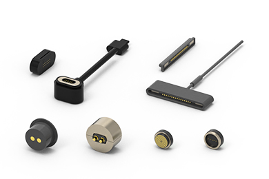
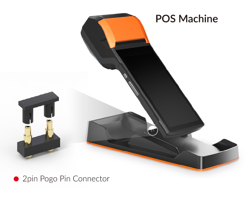
In product designs across smart wearables, medical devices, and industrial equipment, Pogo Pin magnetic connectors are becoming the preferred connection solution for more and more engineers, thanks to their automatic magnetic attraction, stable conductivity, and compact form factor. However, different product structures impose varying requirements on connector mounting methods. So, how exactly are Pogo Pin magnetic connectors installed? This article provides a systematic breakdown of four mainstream mounting solutions.
1. Connector Mounting Depends on Structural Design
The Pogo Pin magnetic connector installation is closely tied to the structural design of the pin tails. Different tail configurations determine how the connector interfaces with the PCB or cables. Based on the spatial constraints, soldering processes, and operating environments of customer products, CFE offers a range of mounting options to ensure precise positioning, reliable soldering, and stable performance.
2. Four Mainstream Mounting Methods Explained
2.1 DIP Type (Through-Hole Insertion)
Installation process: Pre-drilled holes are prepared on the PCB, into which the connector pins are vertically inserted, followed by wave soldering or manual soldering.
Best suited for: Industrial equipment, robotics, power modules, and other applications requiring high mechanical strength and soldering integrity.
2.2 Right-Angle Type
Installation process: The connector pins are bent at an angle before being inserted into the PCB, allowing the connector body to sit flush against the board surface.
Best suited for: Ultra-thin smart wearables, handheld terminals, portable medical devices, and other products with strict height limitations.
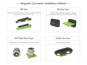
2.3 SMT Mounting Type (Surface-Mount Technology)
Installation process: The connector features a flat-bottomed SMD structure that is placed directly onto PCB pads and secured through a reflow soldering process.
Best suited for: Consumer electronics, smartwatches, TWS earbuds, AI smart glasses, and other high-volume, compact products.
2.4 Solder-Cup Type (Cable Soldering)
Installation process: The connector tail is designed as a solder cup or wire termination structure, allowing wires to be soldered directly to the connector without the need for a PCB.
Best suited for: Battery pack connections, charging dock cables, internal module jumper wires, and similar applications.
3. Mounting Method Comparison Chart
|
Mounting Method |
Connection Type | Key Advantages | Typical Applications |
|
DIP Type |
Through-hole soldering | Precise positioning, strong solder joints, high mechanical stability | Industrial equipment, robotics |
|
Right-Angle Bent Type |
Bent pin soldering | Low profile, parallel to PCB, space-efficient |
Ultra-thin wearables, handheld devices |
| SMT Type |
Surface-mount soldering |
Compact size, simplified PCB design, automation-ready |
Consumer electronics, smart wearables |
| Solder-Cup Type | Direct wire soldering | Flexible, no PCB required, simplified system architecture |
Battery packs, charging docks |

4. FAQ
Q1: How do I choose among the four mounting methods?
The choice depends primarily on three factors: available internal space (PCB area and height clearance), production process (whether reflow or wave soldering is supported on your assembly line), and mechanical strength requirements (whether the connector must withstand repeated mating forces or cable pull forces). We recommend engaging with your connector supplier early in the design phase to optimize PCB layout and mounting strategy.
Q2: Can SMT-mounted magnetic connectors withstand repeated mating cycles?
Yes. The solder joint strength of SMT-mounted connectors is designed to handle normal-use repeated attachment and detachment. For high-frequency mating applications or scenarios with significant pull forces, we recommend adding auxiliary locating holes or reinforced solder pads on the PCB to further enhance soldering reliability.
Q3: What are the PCB layout considerations for right-angle bent connectors?
The key requirement is that the connector body remains flush and parallel to the PCB surface. This means accurate hole positioning and precise control over bend angle and dimensions are essential. We recommend coordinating with your connector supplier during the PCB layout stage to confirm bend direction, dimensions, and tolerances, thereby avoiding interference with surrounding components.
Conclusion
The Pogo Pin magnetic connector installation method directly affects both production efficiency and long-term reliability. With four mainstream options—DIP, right-angle bent, SMT, and solder-cup—CFE provides comprehensive solutions tailored to diverse product structures. Whether you are developing high-volume consumer electronics or high-reliability industrial equipment, CFE offers professional and dependable connection solutions. For selection assistance or custom requirements, please feel free to reach out.